
 English
 Português
 Indonesia
Submit feedback
Polyurethane Eagle Timing Belts Post-processing: A Complete Guide
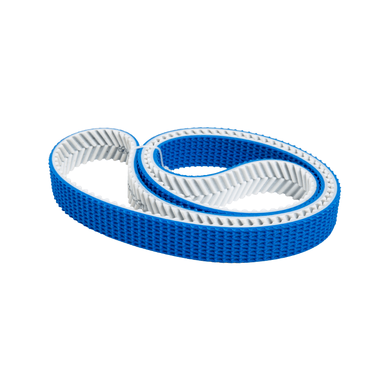
A standard Eagle timing belt leaves the factory ready — but not always ready enough. Depending on the application, the belt straight off the production line may need lower friction on the teeth, a defined surface geometry on the back, integrated mounting fixtures, or precision cutouts for sensor systems. That gap between "standard" and "application-ready" is exactly what post-processing addresses. For Eagle H.O.T. polyurethane timing belts — built from thermoplastic polyurethane with steel tensile cords and a nylon tooth fabric — post-processing unlocks the full range of industrial possibilities these belts are designed for.
Surface Fabric Coatings: PAZ and PAR
Eagle timing belts are produced as standard with a PAZ nylon fabric on the tooth side. This covering reduces the coefficient of friction between tooth and pulley, protects the tooth geometry from wear, and measurably cuts noise — a key reason Eagle belts are already among the quietest synchronous belts on the market.
For applications where the back of the belt contacts a surface, a guide rail, or a driven object, a PAR fabric layer can be applied to the back. PAR increases surface friction and adds a layer of abrasion resistance, making it the preferred option in haul-off systems and laterally guided conveyor setups. Choosing between PAZ-only and a PAZ + PAR combination depends on where contact forces act in the specific drive geometry.
Grinding: Dimensional Accuracy and Friction Control
Three distinct grinding operations serve different engineering purposes. Edge grinding brings belt width into tight dimensional tolerances — critical wherever the belt runs in a groove or channel where thermal expansion and contamination would otherwise cause jamming. Back grinding controls total belt height and, when a rougher finish is specified, increases the coefficient of friction to improve grip on slippery or sensitive transport goods. Profile grinding goes further, introducing complex geometries into the belt back: bevels, slots, oval contours, or user-defined cross-sections that improve product guidance without additional fixtures.
For more on the engineering principles behind these techniques, this detailed breakdown of belt machining methods covers the tolerance ranges and bending stress considerations that drive each process selection.
Milling and Slitting: Managing Bending Stress in Coated Belts
Thicker coatings and back additions increase bending stiffness. When pulley diameters are small, that stiffness translates directly into elevated bending stress — and eventually, coating failure. Two processes address this:
- Slitting cuts the coating at defined intervals across the running direction, reducing effective belt thickness and restoring bending flexibility without compromising the belt body.
- Transverse milling machines relief grooves across the belt back with a controlled radius at the groove base, a better solution when slitting would create unacceptable notch effects in the coating material.
Longitudinal milling serves a different purpose: prismatic or U/V-shaped grooves along the belt length cradle round products — cables, hoses, sausages on food lines — for precise and gentle handling. Pocket milling creates recesses that lock piece goods in position during transport, eliminating the need for separate fixtures.
Punching and Water Jet Cutting
Where the belt surface needs to interact with air or sensors, material removal becomes part of the design. Punching produces clean, repeatable holes used in vacuum conveying systems — the holes allow suction to hold products flat against the belt surface. Water jet cutting handles more complex outlines: irregular profiles, compound cutouts, or contours that would be impractical to punch. Both methods can be applied to the base belt or to an applied coating, and they can be combined with other machining operations in a single production run.
Cleats, V-Guides, and Weld-On Accessories
Eagle belts feature the H.O.T. helical offset tooth profile, which gives them inherent self-tracking behavior — the belt aligns itself on the pulley without flanges. In many drives, this eliminates the need for any lateral guidance at all. Where additional alignment certainty is required, welded V-guides on the back provide a defined tracking path along a grooved pulley or guide rail.
Cleats and baffle plates welded onto the belt surface convert a timing belt into a precision conveyor: inclined transport, product separation, or fixture mounting for jigs and workpiece carriers. Customers specify cleat height, pitch, profile, and attachment method (integrated or welded-on), and custom polyurethane timing belts with pre-welded accessories can be supplied ready to install.
Post-processing is not an afterthought — it is the engineering step that matches belt performance to application reality. For drive systems with non-standard requirements, OEM/ODM custom timing belt development allows these operations to be specified from the outset, with drawings reviewed before production begins.

Contact
-

+86-510-82113539
Shirley: +86-18906170683
Got questions? Call us 24/7 -

[email protected]
Contact us now for a quote -

No.99 Fu Rong Zhong San Rd, Xishan District Economic and Technological Development Zones Wuxi City, Jiangsu, China
Copyright © Wuxi KUEISN Transmission Equipment Co.,Ltd.All Rights Reserved. OEM Industrial Timing Belt and Synchronous Pulley Manufacturer
